
Ancora devo abituarmi all’idea di poter passare una domenica senza toccare un libro universitario. Quante ne ho passate cercando disperatamente di memorizzare e ripassare (in realtà rare volte sono arrivato alla fase di ripasso 😛 ) qualche argomento per gli esami sempre troppo vicini.
Era arrivata l’ora di riempire un pò questo blog, un blog nato come passatempo serale… e che ho lasciato nel dimenticatoio per troppo tempo.
Quale miglior argomento di un pò di codice assembly ARM e GPIO per ricominciare??
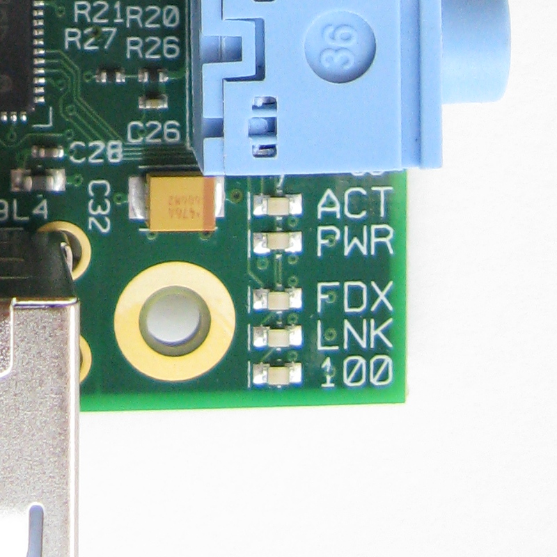
Lo scopo è quello riuscire ad accendere e spegnere un misero led (OK or ACT led per le specifiche Raspberry) collegato al 16esimo pin GPIO (pdf to ARM peripherals) tramite codice scritto direttamente in assembly.
1) Download e Settings ARM Toolchain
La prima cosa da fare è installare una toolchain di sviluppo per processori ARM. Se non volere compilarvi gcc a “manella” potete utilizzare questa toolchain pronta per l’uso ( disponibile per Windows/Linux/MacOS): YAGARTO
Una volta scaricato ed aperto il .dmg, vi chiederà di spostare il file .app in una cartella ed eseguirlo in modo tale da copiare i file binari di gcc in essa.
[sourcecode language=”bash”]unicondor@iMac:yagarto-4.7.2> ls
Binutils.webloc COPYING.LIBGLOSS COPYING3.LIB GNU.webloc arm-none-eabi lib source.txtCOPYING COPYING.NEWLIB GCC.webloc Newlib.webloc bin libexec tools
COPYING.LIB COPYING3 GDB.webloc YAGARTO.webloc include share version.txt
[/sourcecode]
Ora non ci resta altro che includere il percorso di tale cartella nella variabile locale relativo ai vari PATH della nostra shell.
[sourcecode language=”bash”]
unicondor@iMac:yagarto-4.7.2> export PATH=$PATH:$PWD/bin
[/sourcecode]
Se tutto è andato nel verso giusto avrete un output del genere, dove la variabile $PATH conterrà anche il path ai binari di gcc per ARM.
[sourcecode language=”bash”]
unicondor@iMac:yagarto-4.7.2> echo $PATH
/Library/Frameworks/Python.framework/Versions/2.7/bin:/opt/local/bin:/opt/local/sbin:/opt/local/bin:/opt/local/sbin:/opt/local/bin:/opt/local/sbin:/Library/Frameworks/Python.framework/Versions/2.7/bin:/usr/bin:/bin:/usr/sbin:/sbin:/usr/local/bin:/usr/X11/bin:<strong>/Users/unicondor/Documents/Arm_toolchain/yagarto-4.7.2/bin</strong>
[/sourcecode]
2) Download template sviluppo
Per facilitarci ancora di più il compito possiamo procurarci questo template. Composto da una serie di files (sotto elencati) che ci aiuteranno nella compilazione dei nostri sorgenti
[sourcecode language=”text”]
source/
main.s
kernel.ld
LICENSE
Makefile
[/sourcecode]
Dove:
main.s sarà il nostro file sorgenti scritto direttamente in assembly ARM
kernel.ld è usato dal linker per mappare correttamente le zone di memoria (qualche interessante articolo si potrebbe scrivere su questo file)
Makefile spero non ci sia bisogno di spiegazioni 😛
3) Main.s
Ecco il file più importante, il file sorgente scritto direttamente in ARM assembly
[sourcecode language=”bash”]
/*
* .section is a directive to our assembler telling it to place this code first.
* .globl is a directive to our assembler, that tells it to export this symbol
* to the elf file. Convention dictates that the symbol _start is used for the
* entry point, so this all has the net effect of setting the entry point here.
* Ultimately, this is useless as the elf itself is not used in the final
* result, and so the entry point really doesn’t matter, but it aids clarity,
* allows simulators to run the elf, and also stops us getting a linker warning
* about having no entry point.
*/
.section .init
.globl _start
_start:
/*
* This command loads the physical address of the GPIO region into r0.
*/
ldr r0,=0x20200000
/*
* Our register use is as follows:
* r0=0x20200000 the address of the GPIO region.
* r1=0x00040000 a number with bits 18-20 set to 001 to put into the GPIO
* function select to enable output to GPIO 16.
* then
* r1=0x00010000 a number with bit 16 high, so we can communicate with GPIO 16.
*/
mov r1,#1
lsl r1,#18
/*
* Set the GPIO function select.
*/
str r1,[r0,#4]
/*
* Set the 16th bit of r1.
*/
mov r1,#1
lsl r1,#16
/*
* Set GPIO 16 to low, causing the LED to turn on.
*/
str r1,[r0,#40]
/*
* Loop over this forevermore
*/
loop$:
b loop$
[/sourcecode]
Nella sezione references trovate altri esempi da cui questo è stato preso. E’ molto semplice ed intuitivo da capire, inoltre è anche ben commentato per cui posso evitare di spiegare cosa fa 😀
Non dobbiamo fare altro che aggiungere il main.s nella cartella source del template prima scaricato e lanciare la compilazione. Infine avremo il nostro bel kernel.img da poter inserire nella nostra scheda SD e rimpiazzarlo con quello ufficiale di Raspian.
Se tutto e’ andato nel verso giusto, appena inserita l’alimentazione al nostro raspberry si accendera’ il LED ACT…. forse 😛
References
http://www.cl.cam.ac.uk/projects/raspberrypi/tutorials/os/index.html
GitHub
https://github.com/flaviopace/ARM_Assembly_PowerOff-PowerOn_led